
Firmware security 1: Playing with PCI device memory
In this part of the series we will go through the basic of PCI devices and their memory. We will be developing linux kernel driver and using chipsec to analyze the data practically.

In this new series of articles, we will learn about firmware security, i.e things like What included as firmware in a computer? What are the attack vectors? How to protect your firmware? etc. In the first part of the series, I will take you through basic of PCI device and its memory, since everything in firmware somehow depend on them, so you have to learn these before getting more into security specific stuff.
Setup: My setup includes:
- Intel(R) Core(TM) i5-4210U CPU(4th Gen)
- Linux System (kernel 4.19) x86_64
- Chipsec Utility
PCI Basics
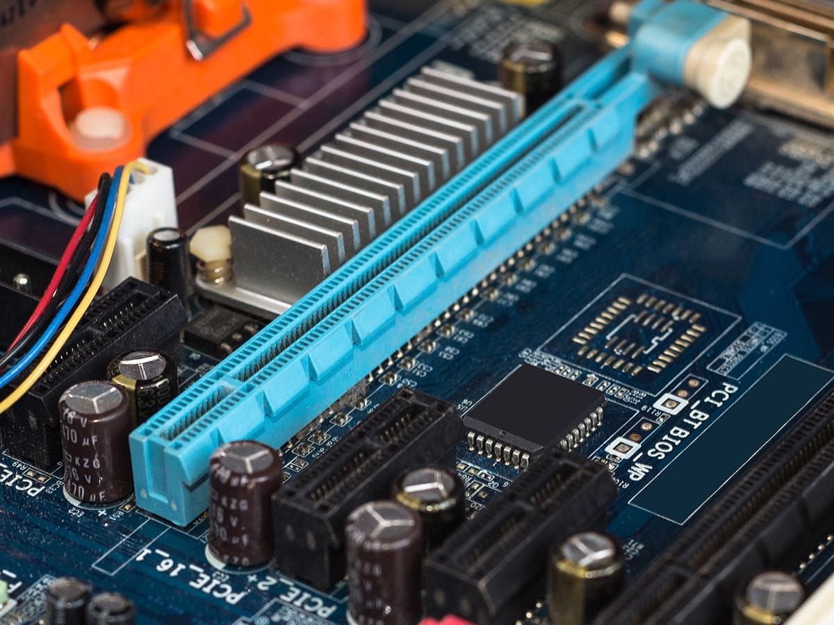
Peripheral Component Interconnect (PCI) is a specification used for connection of computer buses or peripherals devices in motherboard. It is a 32 bit bus which can support 64 bit data transfer by performing 2 32 bit reads. It is an upgraded replacement of ISA bus which only supports 16 bit data transfer. Now PCI is revised with PCIe with almost similar firmware specification but much improved performance.
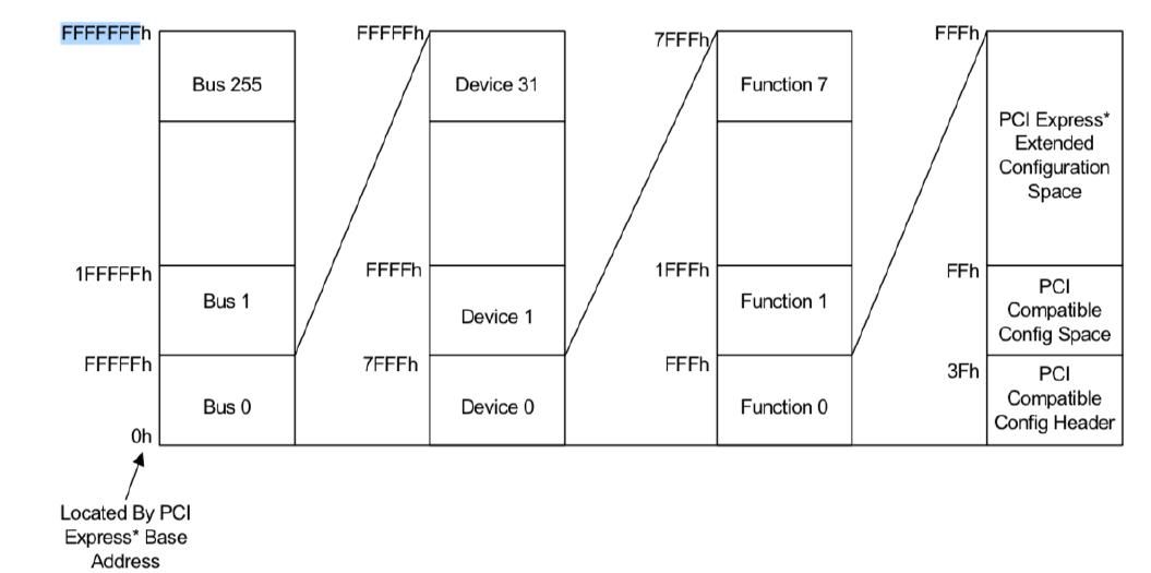
Each PCI bus have devices attached and each device have functions. The topology for PCI bus looks like this:
- Upto 256 Bus
- Each bus have maximum 32 devices attached
- Each device have atmost 8 functions
- Buses are connected using Bridges
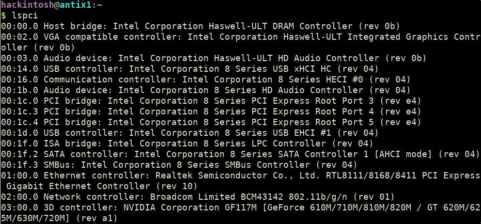
A common way to represent a specific device is using the following format B:D:F (eg 00:1f:0 is LPC controller in my system).
You can check all the PCI devices attached to your processor in linux using lspci command.
PCI Configuration Space
Each PCI device has a PCI Configuration space which is used to store configuration registers. Configuration registers are used for device configuration and communication purposes like identify the device, amount of memory and I/O address space needed by each device, maximum space required by the device etc.
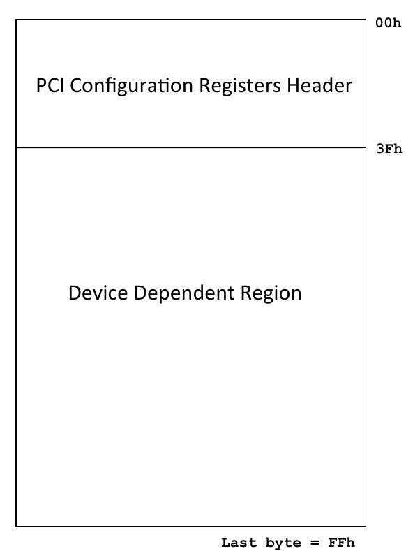
Each PCI device has upto 256 bytes of configuration space whereas PCIe device has 256 bytes + 4KB of extended configuration space. Out of 256 bytes, first 40 bytes are header and remaining bytes are device dependent region.
The registers structure of the header looks mostly like this(differ for PCI-to-PCI bridge and CardBus bridge).
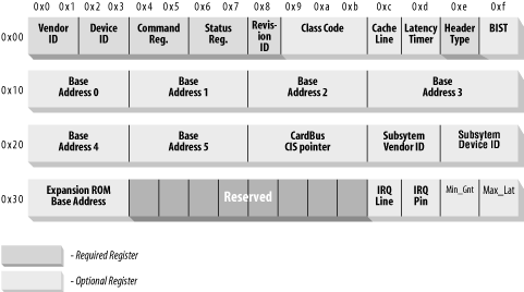
Let's take a look at few registers description, remaining we will check later when they are required.
Vendor Id: Identifies the manufacturer of the device. For eg: 0x8086 for intel devices, 0x10DE for nvidia device.
Device Id: Identifies the particular device by a vendor.
Header Type: Identifies the layout of the rest of the header that begins at byte 0x10 of the header and also specifies whether the device has multiple functions. They can be of three types:
- Type 0: General Device. (Most common one and the one we care in this article.
- Type 1: PCI-to-PCI Bridge
- Type 2: Cardbus Bridge
You can take a look at header structure for each header here: https://wiki.osdev.org/PCI.
Accessing PCI device configuration space
A PCI device configuration space can be accessed using either a through memory request or I/O request. Most PCI device has both mechanism available but PCIe can only be accessed using memory mapped area (sometime I/O access available for Backward compatibility).
Bit 0 in Command register is set then device will respond to I/O space access.
Bit 1 in Command register is set then device will respond to memory space access.
The configuration space can only be accessed from kernel mode, so we will create a simple kernel module for everything we perform below.
A simple layout of kernel module and Makefile for kernel module will look like this:
#include <linux/init.h>
#include <linux/module.h>
#include <linux/pci.h>
#include <linux/slab.h>
#include <linux/interrupt.h>

static int my_init(void)
{
    printk(KERN_INFO "Hello world.\n");
    return  0;
}

static void my_exit(void)
{
    printk(KERN_INFO "Goodbye world.\n");

    return;
}

module_init(my_init);
module_exit(my_exit);

MODULE_LICENSE("GPL");
MODULE_AUTHOR("Shubham Dubey <shubham0d@protonmail.coms>");
MODULE_DESCRIPTION("PCI config MMIO driver");
# Makefile
ifeq ($(KERNELRELEASE),)
KERNELDIR ?= /lib/modules/$(shell uname -r)/build
PWD := $(shell pwd)
modules:
$(MAKE) -C $(KERNELDIR) M=$(PWD) modules EXTRA_CFLAGS="-g -DDEBUG"
modules_install:
$(MAKE) -C $(KERNELDIR) M=$(PWD) modules_install
clean:
rm -rf *.o *~ core .depend .*.cmd *.ko *.mod.c .tmp_versions
.PHONY: modules modules_install clean
else
# called from kernel build system: just declare what our modules are
obj-m := sample_driver.o
endif
Configuration space - I/O Access
Two 32 bit I/O port locations are used to generate configuration space transaction
0xCF8 (CONFIG_ADDRESS)
0xCFC (CONFIG_DATA)
CONFIG_ADDRESS(equivalent of IN operation) is used to define the specific pci device and offset you want to retrieve. The DWORD data get returned using CONFIG_DATA(OUT operation).
32 bit structure for 0xCF8 defines like this:
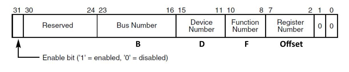
- When bit 31 is set, then only all read and write to CONFIG_DATA will be treated as configuration transaction.
- Bit 24:30 are reserved and should return 0 on read.
- You need to define the B::D::F and offset of configuration space to receive the DWORD value present on that device at a given offset.
We can use inl and outl calls from driver for I/O port operation.
static int my_init(void)
{

	u32 io_addr_response;
	u32 io_data;

	uint32_t address;
	//change according to B::D::F value
    uint32_t lbus  = 0x0;
    uint32_t ldevice = 0x1f;
    uint32_t lfunc = 0x0;
    uint8_t offset = 0x10;

	printk(KERN_INFO "Hello world.\n");

    // create configuration address as per
    address = (uint32_t)((lbus << 16) | (ldevice << 11) |
              (lfunc << 8) | (offset & 0xfc) | ((uint32_t)0x80000000));


	//write the address
	outl(0xCF8, address);

	//check if PCI I/O request to device is enable
	io_addr_response = inl(0xcf8);
	io_addr_response = io_addr_response & 80000000;
	if (io_addr_response == 0)
	{
		printk(KERN_INFO "I/O port access for device is not enabled.\n" );
	}

	io_data = inl(0xcf8);

	printk(KERN_INFO "Data recieved is %x.\n", io_data);

    return  0;
}
After loading the driver you can check the output using sudo dmesg|tail

Note: Above mentioned port I/O transaction will not work with PCIe device because they are mostly only memory mapped. But can work with some for backward compatibilty.
Verifying your output
You can verify your output using chipsec framework. Installation steps are mentioned in repo link.
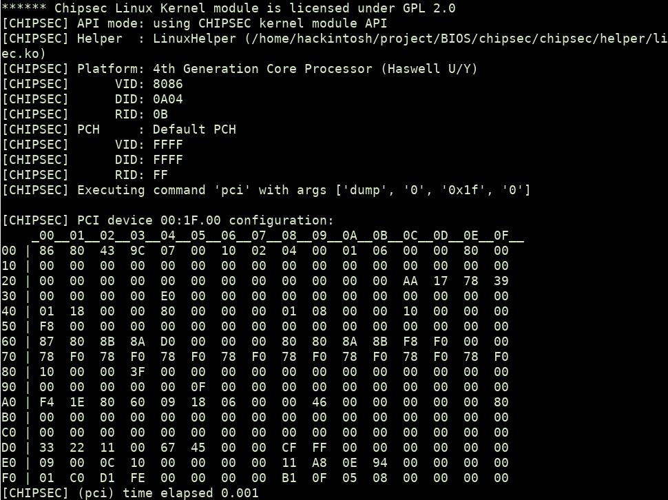
To access the pci device configuration space, you can use following command.
$sudo python chipsec_util.py pci dump 0 0x1f 0The output will look like this:
Configuration space - Memory Access
Another way to access PCI device configuration space is using memory space. Each device is mapped to physical memory, where normal operations like read, write can be performed. For PCI, the memory access is optional but in PCIe device it is mostly the only way available to access PCI data.
We can get the memory mapped configuration space using the following process:
First, find the specific device in the system from list of pci devices.
dev = pci_get_device(vendor_id, device_id) This function scans the list of PCI devices currently present in the system, and if the input arguments match the specified vendor and device IDs, it increments the reference count on the struct pci_dev variable found, and returns it to the caller.
Access the data in BYTE, WORD or DWORD size.
int pci_read_config_byte(struct pci_dev *dev, int offset, u8 *val);
int pci_read_config_word(struct pci_dev *dev, int offset, u16 *val);
int pci_read_config_dword(struct pci_dev *dev, int offset, u32 *val);
Perform write using the following calls:
int pci_write_config_byte(struct pci_dev *dev, int offset, u8 val);
int pci_write_config_word(struct pci_dev *dev, int offset, u16 val);
int pci_write_config_dword(struct pci_dev *dev, int offset, u32 val);
After the driver is done with the struct pci_dev returned by the function, it must call the function pci_dev_put to decrement the usage count properly back to allow the kernel to clean up the device if it is removed.
pci_dev_put(dev)Finding the vendor id and device name
You may think that, to find the device using pci_get_device we need vendor_id and device_id but those value can be found on configuration space only. If you don't have access to configuration space then you can look at device datasheet to get the correct vendor_id and device_id.
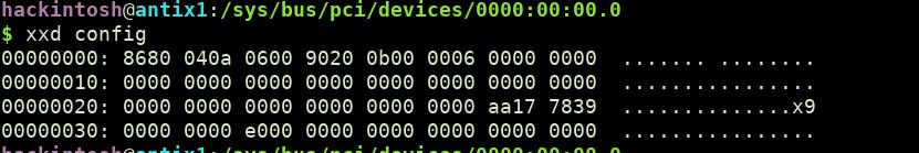
You can also cheat the value from linux pci maintenance code. First 0x40 bytes are mapped to following file location /sys/bus/pci/devices/0000:B:D.F/config.
Another way already mentioned above is using chipsec tool.
So, now let's write the code to retrieve first 4 bytes from device 0:0:0 (DRAM controller in most cases) from MMIO.
static int my_init(void)
{
	struct pci_dev *dev;
	u32 pci_data;
    printk(KERN_INFO "Inside driver.\n");
    //get pci device
    dev = pci_get_device(0x8086, 0x0a0c, NULL);
    if (!dev)
    {
		printk(KERN_INFO "FAILED to get pci device\n");
		pci_dev_put(dev);
		return -ENODEV;
	}
	printk(KERN_INFO "Attached to the pci device\n");
	//read dword value from pci device at offset 0x10
	pci_read_config_dword(dev, 0x10, &pci_data);
	printk(KERN_INFO "PCI configuration space data at offset 0x10 is %x.\n", pci_data);

	//cleanup after use
	pci_dev_put(dev);


    return  0;
}
You will get similar output in dmesg.

Again, you can verify the output using chipsec.
Base Address Registers/ Finding the device memory
Base address registers(BAR) starts at an address 0x10 in the configuration space and will be total 6(BAR[0] to BAR[5]) in number. BARs hold the memory addresses range used by the device. Structure of this register looks like this:
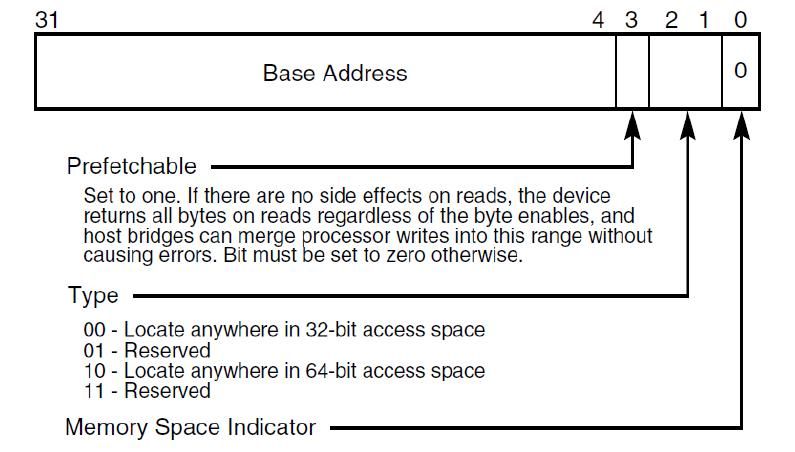
Cleared bit 0 indicate the device is mapped at memory location.
Using above structure, you can derive that, to get the base address, you need to and it with 0xFFFFFFF0 i.e BA[X] = BAR[X] & 0xFFFFFFF0.
For 64 bit space BAR[I] = ((BAR[x] & 0xFFFFFFF0) + ((BAR[x+1] & 0xFFFFFFFF) << 32)).
BAR limit
Each memory block defined by BAR has limit along with base address.
To find the limit, you can write all 1's in that BAR and ~(NOT) the output. i.e ~(BAR[X] & 0xFFFFFFFF).
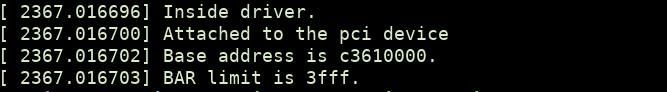
Now let's write a program to get the base address and limit of a BAR.
static int my_init(void)
{
	struct pci_dev *dev;
	u32 pci_data;
    printk(KERN_INFO "Inside driver.\n");
    //get pci device
    dev = pci_get_device(0x8086, 0x0a0c, NULL);
    if (!dev)
    {
		printk(KERN_INFO "FAILED to get pci device\n");
		pci_dev_put(dev);
		return -ENODEV;
	}
	printk(KERN_INFO "Attached to the pci device\n");

	//read dword value from pci deevice
	pci_read_config_dword(dev, 0x10, &pci_data);

	// getting the base address
	pci_data = pci_data & 0xFFFFFFF0;
	printk(KERN_INFO "Base address is %x.\n", pci_data);

	// Getting the PIC device BAR limit
	pci_write_config_dword(dev, 0x10, 0xFFFFFFFF);

	pci_read_config_dword(dev, 0x10, &pci_data);
	pci_data = pci_data & 0xFFFFFFF0;
	pci_data = ~pci_data;
	printk(KERN_INFO "BAR limit is %x.\n", pci_data);

	//cleanup after use
	pci_dev_put(dev);


    return  0;
}
You will receive the similar kind of output in kernel logs:
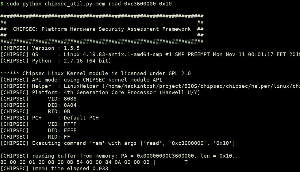
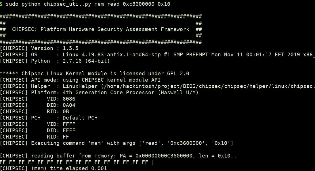
Verifying the BAR output
We can read data directly at a physical address using chipsec. To verify if the base address is correct, read that physical memory location before writing the 0xFFFFFFFF(to get the BAR limit) to the BAR and check the bytes. After writing to BAR, check the base address again. You will notice the bytes get replaced with 0xFF. This happens because after changing the BAR, the device is no longer mapped to the previous location.
You can use following chipsec syntax to read physical memory
sudo python chipsec_util.py mem read address no_of_bytesEx: For BAR 0xc3600004, data at base address before and after changing base address.
PCIe configuration space
Let's move to more recent protocol PCIe related stuff. PCIe has up to 4kb of configuration space(PCI config space + extended config space), which is always mapped to memory and cannot be accessed using the legacy PCI method (through ports 0xCF8 and 0xCFC). The extended space can be located either just after the 256 byte of configuration space or at MMIO location specify by RCRB (Root Complex Register Block).
Till now, we have accessed the memory mapped configuration space using pci_read_config_dword() but we can also manually access the physical address where the configuration space is mapped, only if we know the Base address of PCI configuration space. This will also help to access the PCIe configuration space.
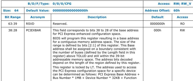
BIOS on boot set PCIEXBAR register(64 bit) to a memory location where it wants the memory controller to start routine to PCI space. The space structure looks like this.
You can use following decoding to read an offset in a PCI device using PCIEXBAR.
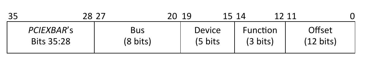
Finding PCIEXBAR: You can check your processor datasheet to confirm the PCI device and offset, where the PCIEXBAR register is located. For intel processor you can download the datasheets from here. For the processor that I am using(Intel 4th gen), this register is located at 0:0:0 (DRAM Controller) at offset 0x60.
Using the above information, let's try to access the first 4 bytes of device 0:0:0.
static int my_init(void)
{
	struct pci_dev *dev;
	u32 pciexbar;
	uint32_t pci_data;
	uint32_t lbus  = 0x0;
    uint32_t ldevice = 0x0;
    uint32_t lfunc = 0x0;
    uint16_t offset = 0x2;
    printk(KERN_INFO "Inside driver.\n");
    //get pci device
    dev = pci_get_device(0x8086, 0x0A04, NULL);
    if (!dev)
    {
		printk(KERN_INFO "FAILED to get pci device\n");
		pci_dev_put(dev);
		return -ENODEV;
	}
	printk(KERN_INFO "Attached to the pci device\n");
	//read PCIEXBAR value
	pci_read_config_dword(dev, 0x60, &pciexbar);

	// retrieving pci configuration space starting address
	pciexbar = pciexbar & 0xF0000000;
	printk(KERN_INFO "PCI Configuration space starts at %x.\n", pciexbar);

	// retrieving the DWORD value for pci device 0:0:0 offset 2
	pci_data = (uint32_t)(pciexbar | (lbus << 20) | (ldevice << 15) | (lfunc << 12) | (offset & 0xFFF));
	printk(KERN_INFO "PCI device data is at physical location %x.\n", pci_data);


	//cleanup after use
	pci_dev_put(dev);


    return  0;
}
You will receive the similar output:
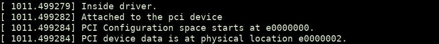
You can now retrieve the data using chipsec:
$sudo python chipsec_util.py mem read 0xe0000002 0x10The returned data should be present at configuration space for device 0:0:0 at offset 0x2. After 256 bytes you will start seeing the bytes from extended configuration space.
You can find the sample code from the post here.
We have already cover enough stuff about PCI devices memory till now, so it's time to end this part here. In the next part, we will discuss PCI expansion roms and majorly go through security issues related to PCI based architecture. Stay tuned!!
Reference:
https://opensecuritytraining.info/IntroBIOS.html
https://wiki.osdev.org/PCI
https://www.oreilly.com/library/view/linux-device-drivers/0596005903/ch12.html#linuxdrive3-CHP-12-FIG-2